|
|
Available in LEADTOOLS Imaging Pro, Vector, Document, and Medical Imaging toolkits. |
|
|
Available in LEADTOOLS Imaging Pro, Vector, Document, and Medical Imaging toolkits. |
Setting Rectangles
|
Note: |
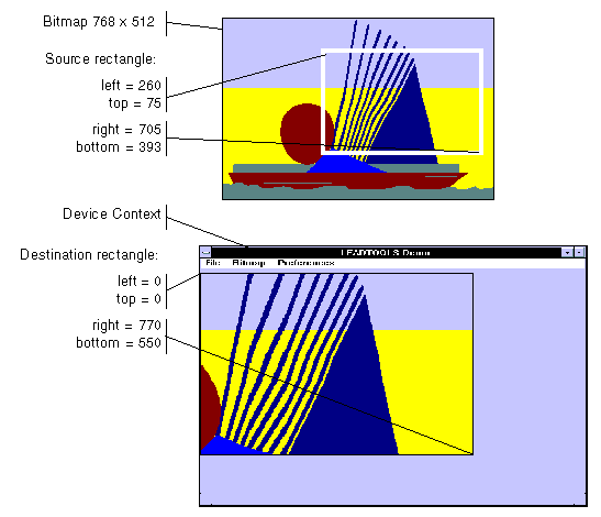
These illustrations are for a bitmap with a TOP_LEFT view perspective. For an explanation of bitmap coordinates and view perspectives, refer to Accounting for View Perspective. If the bitmap is not in TOP_LEFT view perspective, refer to Changing Bitmap Coordinates. |

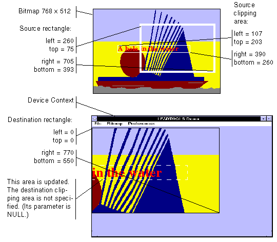
In addition, you can specify a clipping area within either rectangle to limit the area to be painted. For the destination rectangle, a clipping area is commonly specified to repaint part of the image that was temporarily covered up. For a source rectangle, you can use a clipping area to update the display when only part of the image in the source rectangle has changed.
The following illustration shows how specifying a source clipping area affects the display. Text has been added to the source bitmap (using the bitmap as a display surface), and the source clipping area specifies the area to be repainted.

You can specify the various rectangles in any way that meets your needs. Coordinates can have negative values and they can extend beyond the bounds of the bitmap or the device context. In fact, it is common for the display rectangle to be bigger than the device context, where scroll bars are used to see different parts of the image.