|
Available in LEADTOOLS Imaging Pro, Vector, Document, and Medical Imaging toolkits. |
LPaint::PaintDC
#include "ltwrappr.h"
virtual L_INT LPaint::PaintDC(uROP3=SRCCOPY)
|
L_UINT32 uROP3; |
/* windows ROP code for display */ |
Displays the class object's associated bitmap to the current device context (which can be a screen, printer, or memory dc). If the display surface has fewer colors than the image, this function dithers the output to that display surface without affecting the actual image data.
|
Parameter |
Description |
|
uROP3 |
The Windows ROP code that determines how the destination rectangle is updated. This parameter takes the same codes as the Windows BitBlt() function. For ordinary painting, use SRCCOPY. |
Returns
|
SUCCESS |
The function was successful. |
|
< 1 |
An error occurred. Refer to Return Codes. |
Comments
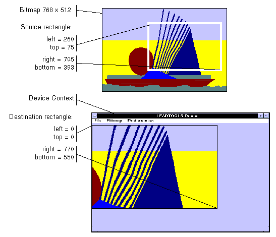
This function uses the rectangles specified by the following functions:
Scaling of the displayed image depends on the relationship between these two rectangles, as shown in the following illustration.
The mapping mode of this object's device context must be MM_TEXT.
|
Note: |
These illustrations are for a bitmap with a TOP_LEFT view perspective. For an explanation of bitmap coordinates and view perspectives, refer to Accounting for View Perspective. If the bitmap is not in TOP_LEFT view perspective, refer to Changing Bitmap Coordinates. |

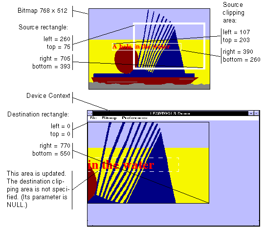
In addition, you can specify a clipping area within either rectangle to limit the area to be painted. For the destination rectangle, a clipping area is commonly specified to repaint part of the image that was temporarily covered up. For a source rectangle, you can use a clipping area to update the display when only part of the image in the source rectangle has changed.
The following illustration shows how specifying a source clipping area affects the display. Text has been added to the source bitmap (using the bitmap as a display surface), and the source clipping area specifies the area to be repainted.

You can specify the various rectangles in any way that meets your needs. Coordinates can have negative values and they can extend beyond the bounds of the bitmap or the device context. In fact, it is common for the display rectangle to be bigger than the device context, where scroll bars are used to see different parts of the image.
In simple cases, you can do the following:
LBitmapBase::SetSrcRect(NULL);
//Use the source default RECTS
LBitmapBase::SetClipSrcRect(NULL); //Use the source default RECTS
LBitmapBase::SetDstRect(prcDst); //Use 0, 0 and bitmap dimensions for
the destination RECT
LBitmapBase::SetClipDstRect(prcClipDst); // Use the destination rectangle
returned by WM_PAINT
To get the current settings for the display rectangles, call LBitmapBase::GetRects.
If indexed painting is used (see LBitmapBase::SetDisplayMode), then palette colors are not passed to the DC, only the palette indices are passed. Before painting, the right palette must be selected and realized to the DC.
Required DLLs and Libraries
|
LTDIS For a listing of the exact DLLs and Libraries needed, based on the toolkit version, refer to Files To Be Included With Your Application. |
Win32, x64.
See Also
|
Functions: |
Class Members, LFile::LoadCMYKArray, LFile::SaveCMYKArray, LPaint::PaintDCCMYKArray, LBitmapBase::RectToBitmap, LBitmapBase::RectFromBitmap |
|
Topics: |
|
|
|
|
|
|
Example
#define MAKE_IMAGE_PATH(pFileName) TEXT("C:\\Users\\Public\\Documents\\LEADTOOLS Images\\")pFileName
L_INT LPaint__PaintDCExample(HDC hDC)
{
   L_INT nRet;
   LBitmap MyBitmap;
   nRet = MyBitmap.Load(MAKE_IMAGE_PATH(TEXT("image1.cmp")));
   if(nRet != SUCCESS)
      return nRet;
   LPaint MyPaint(&MyBitmap, hDC);
   nRet = MyPaint.PaintDC();
   if(nRet != SUCCESS)
      return nRet;
   return SUCCESS;
}