| LEADTOOLS Multimedia API Help > Add-on Modules > LEADTOOLS MPEG2 Transport Module > LEADTOOLS DVR Components > Programming with the DVR Components of the LEADTOOLS MPEG-2 Transport Module |
The DVR components of the LEADTOOLS MPEG-2 Module make it possible to buffer and playback captured data from live and streaming video sources. The DVR components are comprised of two main interfaces DVR Sink and DVR Source . The DVR Sink interface is responsible for writing buffer files containing previously captured multiplexed stream data. The DVR Source interface provides an IFileSourceFilter based filter capable of reading the DVR buffer list ( .LBL ) file and playing its captured data located in the recording chunk ( .LRC ) files.
With the LEAD DVR Source interface, you can pause, rewind and fast-forward by seeking through the captured buffer data from both live video sources and UDP and TCP streams. This buffered data can also be copied as segments from the DVR buffer files. Also, the captured data arriving from the source can be written to a separate backup file .
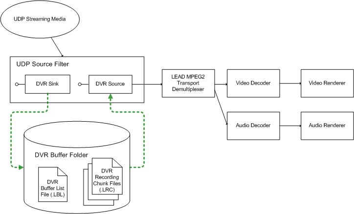
Figure 1 illustrates a DirectShow filter graph using the LEAD MPEG2 Transport UDP Source filter , which internally uses the DVR Sink and DVR Source filters to implement buffered capture and playback.

Figure 1. Implementation of streaming media capture using the LEAD MPEG2 Transport UDP Source Filter.
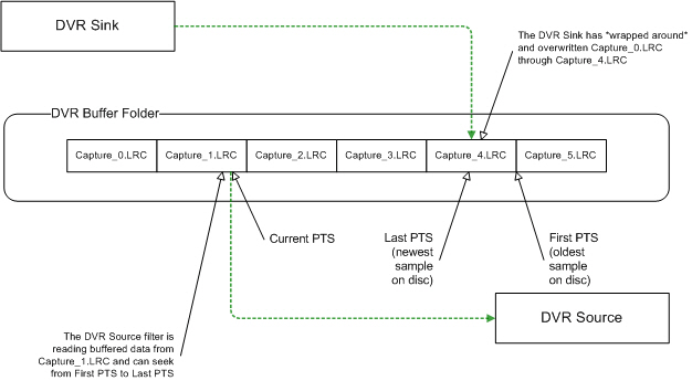
At any given time, during DVR buffered capture and playback, there is a group of buffer files that are being written and read. Figure 2 illustrates the DVR buffer data queueing strategy, with respect to DVR Sink write operations and DVR Source read operations.

Figure 2. DVR streaming media buffered-capture strategy
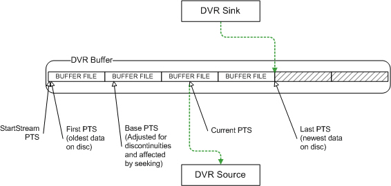
While it is not necessary to know the details of the DVR buffer storage implementation, it is still important to understand the configuration of DVR buffer files as they relate to buffered video playback, seek and pause operations. The design of the DVR buffer queues is straightforward, but the implementation details can be subtle. The underlying data structure of the buffer storage and the buffer files comprising it is that of a circular queue . Figure 3 shows the state of the DVR buffer queue storage shortly after the start of the filter graph. The buffer folder has a FileCount of 6, but only 4 files have been created thus far:

Figure 3. DVR Buffer queue storage state
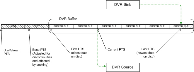
In this example, the buffer storage includes a buffer FileCount value of 6. As the circular buffer becomes full, new data arriving from the DVR Sink must still be stored. The oldest buffer file will be recycled (all previous stored data is discarded) and newly received data is written to the file. Figure 4 illustrates the buffer condition of lost data and buffer file reuse:

Figure 4. DVR buffer state as queue files are recycled
Notice that the StartStreamPTS and BaseStreamPTS values in the above example refer to buffered data that was discarded to make room for new data. These values are still important for calculations of absolute and relative (DirectShow) stream times. See the table below for the different PTS time stamp values and how they are used to manage access and playback of the DVR buffer data.
Table 1. DVR Buffer Queue Times
|
Time |
Remarks |
|
StartStreamPTS |
First available data at the start of the last seek operation. |
|
BaseStreamPTS |
The position in the stream where we last sought. |
|
FirstStreamPTS |
The oldest data in the buffer. |
|
LastStreamPTS |
The newest data in the buffer. |
|
CurrentStreamPTS |
Current position according to the Demultiplexer. (A more precise position is given by the renderer through the get_CurrentPosition method). |
Table 2. Units of Time
|
Units |
Remarks |
|
PTS |
Presentation Time Stamp (90,000 PTS units in 1 second) |
|
Seconds |
= PTS / 90000 |
|
PTS |
= 90000 * Seconds |
|
Absolute Time (seconds) |
= ( Current PTS - Stream Start PTS ) / 90000 |
|
DirectShow Time (REFERENCE_TIME) |
= ( Current PTS - Base ) / 90000 |
The methods and properties provided by the DVR components are:
ILMDVRSink::put_FolderCount, ILMDVRSink::put_FolderName, and ILMDVRSink::put_BaseName Properties to set buffer folder count, folder locations and filename.
ILMDVRSink::SetBufferSize Method to set the size and count of buffer files.
ILMDVRSink::GetAvailabilityInfo Method to check data availability.
ILMDVRSink::GetBufferTotalSize Method to get the current and maximum allowed number of buffer files.
ILMDVRSink::CopyBufferToFile Method to copy buffer data to a new file.
ILMDVRSink:: StartBackupToFile and ILMDVRSink:: StopBackupToFile Methods to start and stop backup file writer.
ILMDVRSink::GetStatus Method to get the current sink status.
ILMDVRSink::GetBufferInfo Method to get current information about a buffer folder.
ILMDVRSource::ReadData Method to read data directly from the DVR buffers using starting offset and desired read size.
ILMDVRSink::CreateEvents and ILMDVRSink::FreeEvents Method to use windows event notifications to monitor buffer writes and buffer list changes.
Functions used to optimize DVR Sink performance when attributes are changed:
ILMDVRSink::StartChangingAttributes Method to start changing buffer configuration settings.
ILMDVRSink::StopChangingAttributes Method to apply or cancel changed buffer settings.
For programming examples and tutorials on using the DVR components features, please see the following How To examples:
See Also
DVR and MPEG2Transport Demo projects (A complete set of example application projects)
Licensing
In order to deploy the MPEG-2 Transport Module specialized components, you must complete the Deployment License Application form (which can be found in the LEADTOOLS Licensing Help File under the topic, "Deployment License Application"), and procure any necessary deployment licenses. If you have any questions concerning licensing the codecs/filters, you can contact LEAD licensing at licensing@leadtools.com.